Categories
- Pipe & Tube (18)
- Flange & Fitting (97)
- Fastener & Gasket (12)
- Valve & Pump (18)
- Base Material (11)
- Equipment (8)
- Application (30)
- Technical (110)
The ASME B16.47 flanges refer to large diameter pipe flanges manufactured in accordance with ASME B16.47, which covers pressure-temperature ratings, materials, dimensions, tolerances, marking, and testing for the flanges. These flanges can be provided in sizes NPS 26 through NPS 60 with rating class designations 75, 150, 300, 400, 600, and 900. NPS is the designation for nominal flange size. It is related to the reference nominal diameter, DN, used in international and other standards. For flange sizes covered in ASME B16.47, the relationship is DN = 25 × NPS. The standard specification states values in both SI metric and U.S. Customary units, except that diameter of bolts and flange bolt holes are expressed in inch units only.

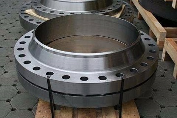
Welding neck flanges 30″ 300# manufactured to ASME B16.47 Series A.
ASME B16.47 provides two series of flange dimensions and two flange types. Series A specifies flange dimensions for general use flanges, which are originated from MSS SP 44 and covering Class 150, Class 300, Class 400, Class 600, and Class 900. Series B specifies flange dimensions for compact flanges that, in most cases, have smaller bolt circle diameters than Series A flanges. At the request of the American Petroleum Institute (API), flange dimensions of ASME B16.47 Series B are provided in accordance with the API standard 605. The two series of flanges are, in general, not interchangeable. Two flange types, welding neck and blind, can be furnished for both series of flanges.

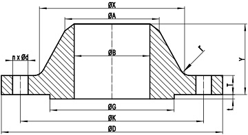
Figure-1: technical drawing for weld neck flange, RF, conforming to ASME B16.47.
ASME B16.47 welding neck flanges should be made from forgings or castings, whilst blind flanges (without hub) may be made from forgings, castings, or plates. The standard has categorized a variety of materials in different material groups which are listed in Table-A below. These materials cover carbon steels, alloy steels, stainless steels and nickel alloys. The possibility of material deterioration in service should be considered by the user. Carbide phase conversion to graphite and excessive oxidation of ferritic materials, susceptibility to intergranular corrosion of austenitic materials, or grain boundary attack of nickel base alloys are among those items requiring attention.

Figure-2: technical drawing of blind flanges with raised face, conforming to ASME B16.47.
Particularly, forged flanges, manufactured according to ASME B16.47 Series A or Series B, shall be manufactured as one piece in accordance with the applicable material specification. The forging process, either die forging or open-die forging, is a compressive plastic hot working operation that consolidates the material to flow in the direction most favorable for resisting the stresses encountered in service.
| Group No. | Forgings | Castings | Plates |
|---|---|---|---|
| 1.1 | A105 | A216 Gr.WCB | A515 Gr.70 |
| 1.1 | A350 Gr.LF2 | - | A516 Gr.70 |
| 1.1 | - | - | A537 Cl.1 |
| 1.1 | A350 Gr.LF6 Cl.1 | - | - |
| 1.1 | A350 Gr.LF3 | - | - |
| 1.2 | - | A216 Gr.WCC | - |
| 1.2 | - | A352 Gr.LCC | - |
| 1.2 | A350 Gr.LF6 Cl2 | - | - |
| 1.2 | - | A352 Gr.LC2 | A203 Gr.B |
| 1.2 | - | A352 Gr.LC3 | A203 Gr.E |
| 1.3 | - | A352 Gr.LCB | A515 Gr.65 |
| 1.3 | - | - | A516 Gr.65 |
| 1.3 | - | - | A203 Gr.A |
| 1.3 | - | - | A203 Gr.D |
| 1.3 | - | A217 Gr.WC1 | - |
| 1.3 | - | A352 Gr.LC1 | - |
| 1.4 | - | - | A515 Gr.60 |
| 1.4 | A350 Gr.LF1 Cl.1 | - | A516 Gr.60 |
| 1.5 | A182 Gr.F1 | - | A204 Gr.A |
| 1.5 | - | - | A204 Gr.B |
| 1.7 | A182 Gr.F2 | - | - |
| 1.7 | - | A217 Gr.WC4 | - |
| 1.7 | - | A217 Gr.WC5 | - |
| 1.9 | - | A217 Gr.WC6 | - |
| 1.9 | A182 Gr.F11 Cl.2 | - | A387 Gr.11 Cl.2 |
| 1.10 | A182 Gr.F22 Cl.3 | A217 Gr.WC9 | A387 Gr.22 Cl.2 |
| 1.11 | - | - | A240 Gr.C |
| 1.13 | A182 Gr.F5a | A217 Gr.C5 | - |
| 1.14 | A182 Gr.F9 | A217 Gr.C12 | - |
| 1.15 | A182 Gr.F91 | A217 Gr.C12A | A387 Gr.91 Cl.2 |
| 1.17 | A182 Gr.F12 Cl.2 | - | - |
| 1.17 | A182 Gr.F5 | - | - |
| 1.18 | A182 Gr.F92 | - | - |
| 2.1 | A182 Gr.F304 | A351 Gr.CF3 | A240 Gr.304 |
| 2.1 | A182 Gr.F304H | A351 Gr.CF8 | A240 Gr.304H |
| 2.2 | A182 Gr.F316 | A351 Gr.CF3M | A240 Gr.316 |
| 2.2 | A182 Gr.F316H | A351 Gr.CF8M | A240 Gr.316H |
| 2.2 | A182 Gr.F317 | - | A240 Gr.317 |
| 2.2 | - | A351 Gr.CG8M | - |
| 2.3 | A182 Gr.F304L | - | A240 Gr.304L |
| 2.3 | A182 Gr.F316L | - | A240 Gr.316L |
| 2.3 | A182 Gr.F317L | - | - |
| 2.4 | A182 Gr.F321 | - | A240 Gr.321 |
| 2.4 | A182 Gr.F321H | - | A240 Gr.321H |
| 2.5 | A182 Gr.F347 | - | A240 Gr.347 |
| 2.5 | A182 Gr. F347H | - | A240 Gr.347H |
| 2.5 | A182 Gr.F348 | - | A240 Gr.348 |
| 2.5 | A182 Gr.F348H | - | A240 Gr.348H |
| 2.6 | - | - | A240 Gr.309H |
| 2.7 | A182 Gr.F310 | - | A240 Gr.310H |
| 2.8 | A182 F44 | A351 CK3MCuN | A240 S31254 |
| 2.8 | A182 F51 | - | A240 S31803 |
| 2.8 | A182 F53 | - | A240 S32750 |
| 2.8 | - | A351 CE8MN | - |
| 2.8 | - | A995 CD4MCu | - |
| 2.8 | - | A995 CD3MWCuN | - |
| 2.8 | A182 F55 | - | A240 32760 |
| 2.9 | - | - | A240 Gr.309S |
| 2.9 | - | - | A240 Gr.310S |
| 2.10 | - | A351 Gr.CH8 | - |
| 2.10 | - | A351 Gr.CH20 | - |
| 2.11 | - | A351 Gr.CF8C | - |
| 2.12 | - | A351 Gr.CK20 | - |
The pressure-temperature ratings indicate the maximum allowable working gage pressures at the temperatures for the applicable material and class designation. The working pressures may be furnished in bar or psi units, whilst the temperatures may be furnished in degrees Celsius or degrees Fahrenheit units. The ASME B16.47 flanges may be applied to services at low temperatures, intermediate temperatures, or high temperatures. The temperature shown for a corresponding pressure rating is the temperature of the pressure-containing shell of the component. In general, this temperature is the same as that of the contained fluid.
Similar to ASME B16.5, the ASME B16.47 flange may be furnished with raised face (RF), flat face (FF), or ring-type joint face (RTJ). Classes 75, 150 and 300 flanges are regularly furnished with a 2 mm raised face. Class 400, 600 and 900 flanges are regularly furnished with a 7 mm raised face. The thickness of the raised face in all cases is in addition to the minimum flange thickness, T. It is recommended that the Class 75 flanges be used only with a 2 mm raised face or flat face. The height of raised portion of the RTJ groove shall be in addition to the minimum flange thickness, T. The raised face may be removed by the user from a raised face flange to convert it to a flat face flange.
Pipe flanges conforming to ASME B16.47 shall be marked by the following method: brand name + material + pressure rating + standard + size + R-number (for a RTJ facing) + heat number. For example: M ASTM A105 Class 600 ASME B16.47 Series A 30″ RF 78580. Flanged joints may be subjected to system pressure tests at a pressure of 1.5 times the 38°C (100°F) rating rounded off to the next higher 1 bar (25 psi) increment. Testing at any higher pressure is the responsibility of the user, taking into account the requirements of the applicable code or regulation.
The dimensional designations of ASME B16.47 weld neck and blind flanges are illustrated in Figure-1 and Figure-2. D: outside diameter of flange; T: minimum thickness of flange; Y: length through hub of WN; X: diameter of hub of WN flange; A: hub diameter of WN at top; G: raised face diameter; K: diameter of bolt circle; n: number of bolt holes; d: diameter of bolt hole; l: diameter of bolt; r: minimum fillet radius of WN. The tolerances are listed in Table-B below.
| Item | Condition | Tolerance |
|---|---|---|
| D | all sizes | ±3.2 |
| K | all sizes | ±1.5 |
| G | all sizes | ±2 |
| t | 2 mm | ±0.5 |
| 7 mm | ±2 | |
| B | all sizes | +3.0 -2.0 |
| A | all sizes | +5.0 -2.0 |
| X | all sizes | ±3.2 |
| T | T ≤ 25 mm | +3.0 -0.0 |
| 25 mm < T ≤ 50 mm | +5.0 -0.0 |
|
| 50 mm < T ≤ 75 mm | +8.0 -0.0 |
|
| T > 75 mm | +10.0 -0.0 |
|
| Y | all sizes | +3.0 -5.0 |
| ASME B16.47 Series A Flanges, by Class | |||||
| 150 | 300 | 400 | 600 | 900 | - |
| ASME B16.47 Series B Flanges, by Class | |||||
| 75 | 150 | 300 | 400 | 600 | 900 |
