Categories
- Pipe & Tube (18)
- Flange & Fitting (97)
- Fastener & Gasket (12)
- Valve & Pump (18)
- Base Material (11)
- Equipment (10)
- Application (31)
- Technical (110)
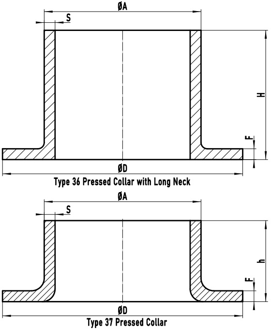
Figure-1: The technical drawing of EN 1092-1 Type 36 pressed collar with long neck and Type 37 pressed collar. ΦD: facing diameter; ΦA: outside diameter of neck; S: wall thickness; F: collar thickness; H & h: length of pressed collar; Mass1: mass/weight of type 36 pressed collar with long neck; Mass2: mass/weight of type 37 pressed collar.
As illustrated in Figure-1, EN 1092-1 Type 36 and Type 37 pressed collars consist of two sections: the straight pipe length and the lapped (or flared) pipe end. The major distinction between the two types is the total length: Type 36 has extended length compared to Type 37. That is why Type 36 is featured with “long neck”. Both collars shall always be used with a Type 02 loose plate flange, which slips over through the straight length till it reached the back face of the lapped end. Fasteners are applied to compress the jointing face of the collar against the gasket. Thus, Type 36 and Type 37 pressed collars have exactly the same function as that of an ASME B16.9 lap joint stub end. They are generally available in p/T ratings of PN 2.5, PN 6, PN 10 and PN 16, and in sizes from DN 10 to DN 200.
| EN 1092-1 Loose Plate Flanges & Collars | |||
|---|---|---|---|
| Type 02 | Type 04 | Type 32 | Type 33 |
| Type 34 | Type 35 | Type 36 | Type 37 |
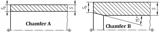
Chamfer A and Chamfer B for Type 36 and Type 37 pressed collars.
Two types of weld ends for pressed collar Type 36 and Type 37 may be furnished: Chamfer A and Chamfer B. For sizes no greater than DN 100, Chamfer A shall be furnished with square-cut ends; For sizes greater than DN 100, the welding ends shall be finished to a slight chamfer of 15° with tolerance of (+5°, -0°), which is defined as Chamfer B.
The EN 1092-1 Type 36 and Type 37 may be manufactured of austenitic stainless steels, duplex stainless steels (austenitic-ferritic), titanium, nickel, tantalum or other corrosion-resistant alloys. The Type 37 pressed collar is usually pressed from welded or seamless pipes, while the Type 36 pressed collar with long neck is usually manufactured by a forging process. Moreover, if welding is performed during the manufacture, it shall have full penetration. One of the NDT methods shall be conducted for the welds: visual inspection (VT), radiography (RT), ultrasonic testing (UT), penetrant testing (PT), and magnetic particle test (MT). The surface finishes for both outside diameter and center bore diameter shall be Ra≤25μm & Rz≤160μm. If it is manufactured by a pressing/lapping process, the surface finish for jointing faces shall be as formed. If it is manufactured by a forging process, the jointing face shall be furnished by a turning process with surface finish of 3.2μm≤Ra≤12.5μm & 12.5μm≤Rz≤50μm.
| ΦA | PN 2.5 to PN 10 | |||
| Type 36 | Type 37 | Type 36 | Type 37 | |
| S | Sp | S | Sp | |
| 17.2 | 2 | 2 | 2 | 2 |
| 21.3 | 2 | 2 | 2 | 2 |
| 26.9 | 2.6 | 2.6 | 2 | 2 |
| 33.7 | 2.6 | 2.6 | 2 | 2 |
| 42.4 | 3.2 | 3.2 | 2 | 2 |
| 48.3 | 3.2 | 3.2 | 2 | 2 |
| 60.3 | 3.2 | 3.2 | 2 | 2 |
| 76.1 | 3.2 | 3.2 | 2 | 2 |
| 88.9 | 3.2 | 3.2 | 2 | 2 |
| 114.3 | 3.2 | 3.2 | 3.2 | 3.2 |
| 139.7 | 4 | 3.2 | 3.2 | 3.2 |
| 168.3 | 5 | 3.2 | 3.5 | 3.2 |
| 219.1 | 5 | 3.2 | 4.5 | 3.2 |
| 273 | 8 | 3.2 | - | - |
| 323.9 | 8 | 3.2 | - | - |
| 355.6 | 8 | 3.2 | - | - |
| 406.4 | 8 | 3.2 | - | - |
| 457 | 8 | 3.2 | - | - |
| 508 | 8 | 3.2 | - | - |
| ΦA | PN 16 | |||
| Type 36 | Type 37 | Type 36 | Type 37 | |
| S | Sp | S | Sp | |
| 17.2 | 2 | 2 | 2 | 2 |
| 21.3 | 2 | 2 | 2 | 2 |
| 26.9 | 2.6 | 2.6 | 2 | 2 |
| 33.7 | 2.6 | 2.6 | 2 | 2 |
| 42.4 | 3.2 | 3.2 | 2 | 2 |
| 48.3 | 3.2 | 3.2 | 2 | 2 |
| 60.3 | 3.2 | 3.2 | 2 | 2 |
| 76.1 | 3.2 | 3.2 | 2 | 2 |
| 88.9 | 3.2 | 3.2 | 2 | 2 |
| 114.3 | 3.2 | 3.2 | 3.2 | 3.2 |
| 139.7 | 4 | 3.2 | 3.5 | 3.2 |
| 168.3 | 5 | 3.2 | 4.5 | 3.2 |
| 219.1 | 6 | 3.2 | 5.6 | 3.2 |
| 273 | 10 | 3.2 | - | - |
| 323.9 | 10 | 4 | - | - |
| 355.6 | 10 | 4 | - | - |
| 406.4 | 10 | 4 | - | - |
| 457 | - | - | - | - |
| 508 | - | - | - | - |
| DN | D PN 2.5 mm | D PN 6 mm | D PN 10 mm | D PN 16 mm |
|---|---|---|---|---|
| 10 | 35 | 35 | 40 | 40 |
| 15 | 40 | 40 | 45 | 45 |
| 20 | 50 | 50 | 58 | 58 |
| 25 | 60 | 60 | 68 | 68 |
| 32 | 70 | 70 | 78 | 78 |
| 40 | 80 | 80 | 88 | 88 |
| 50 | 90 | 90 | 102 | 102 |
| 65 | 110 | 110 | 122 | 122 |
| 80 | 128 | 128 | 138 | 138 |
| 100 | 148 | 148 | 158 | 158 |
| 125 | 178 | 178 | 188 | 188 |
| 150 | 202 | 202 | 212 | 212 |
| 200 | 258 | 258 | 268 | 268 |
| 250 | 312 | 312 | 320 | 320 |
| 300 | 365 | 365 | 370 | 378 |
| 350 | 415 | 415 | 430 | 438 |
| 400 | 465 | 465 | 482 | 490 |
| 450 | 520 | 520 | 532 | 550 |
| 500 | 570 | 570 | 585 | 610 |
| DN | F for Type 36 mm PN 2.5 | F for Type 37 mm PN 2.5 | F for Type 36 mm PN 6 | F for Type 37 mm PN 6 |
|---|---|---|---|---|
| 10 | 2 | 2.5 | 2 | 2.5 |
| 15 | 2 | 2.5 | 2 | 2.5 |
| 20 | 2.5 | 3 | 2.5 | 3 |
| 25 | 2.5 | 3 | 2.5 | 3 |
| 32 | 3 | 3 | 3 | 3 |
| 40 | 3 | 3 | 3 | 3 |
| 50 | 3 | 3 | 3 | 3 |
| 65 | 3 | 3 | 3 | 3 |
| 80 | 3 | 3 | 3 | 3 |
| 100 | 4 | 4 | 4 | 4 |
| 125 | 4 | 4 | 4 | 4 |
| 150 | 5 | 4 | 5 | 4 |
| 200 | 5 | 5 | 5 | 5 |
| 250 | 8 | - | 8 | - |
| 300 | 8 | - | 8 | - |
| 350 | 8 | - | 8 | - |
| 400 | 8 | - | 8 | - |
| 450 | 8 | - | 8 | - |
| 500 | 8 | - | 8 | - |
| DN | F for Type 36 mm PN 10 | F for Type 37 mm PN 10 | F for Type 36 mm PN 16 | F for Type 37 mm PN 16 |
|---|---|---|---|---|
| 10 | 2 | 2.5 | 2 | 2.5 |
| 15 | 2 | 2.5 | 2 | 2.5 |
| 20 | 2.5 | 3 | 2.5 | 3 |
| 25 | 2.5 | 3 | 2.5 | 3 |
| 32 | 3 | 3 | 3 | 3 |
| 40 | 3 | 3 | 3 | 3 |
| 50 | 3 | 3 | 3 | 3 |
| 65 | 3 | 3 | 3 | 3 |
| 80 | 3 | 3 | 3 | 3 |
| 100 | 4 | 4 | 4 | 4 |
| 125 | 4 | 4 | 4 | 4 |
| 150 | 5 | 4 | 5 | 5 |
| 200 | 5 | 5 | 6 | 6 |
| 250 | 8 | - | 10 | - |
| 300 | 8 | - | 10 | - |
| 350 | 8 | - | 10 | - |
| 400 | 8 | - | 10 | - |
| DN | H for Type 36 mm PN 2.5 | h for Type 37 mm PN 2.5 | H for Type 36 mm PN 6 | h for Type 37 mm PN 6 |
|---|---|---|---|---|
| 10 | 35 | 7 | 35 | 7 |
| 15 | 38 | 7 | 38 | 7 |
| 20 | 40 | 8 | 40 | 8 |
| 25 | 40 | 10 | 40 | 10 |
| 32 | 42 | 12 | 42 | 12 |
| 40 | 45 | 15 | 45 | 15 |
| 50 | 45 | 20 | 45 | 20 |
| 65 | 45 | 20 | 45 | 20 |
| 80 | 50 | 25 | 50 | 25 |
| 100 | 52 | 25 | 52 | 25 |
| 125 | 55 | 25 | 55 | 25 |
| 150 | 55 | 25 | 55 | 25 |
| 200 | 62 | 30 | 62 | 30 |
| 250 | 68 | - | 68 | - |
| 300 | 68 | - | 68 | - |
| 350 | 68 | - | 68 | - |
| 400 | 72 | - | 72 | - |
| 450 | 72 | - | 72 | - |
| 500 | 75 | - | 75 | - |
| DN | H for Type 36 mm PN 10 | h for Type 37 mm PN 10 | H for Type 36 mm PN 16 | h for Type 37 mm PN 16 |
|---|---|---|---|---|
| 10 | 35 | 7 | 35 | 7 |
| 15 | 38 | 7 | 38 | 7 |
| 20 | 40 | 8 | 40 | 8 |
| 25 | 40 | 10 | 40 | 10 |
| 32 | 42 | 12 | 42 | 12 |
| 40 | 45 | 15 | 45 | 15 |
| 50 | 45 | 20 | 45 | 20 |
| 65 | 45 | 20 | 45 | 20 |
| 80 | 50 | 25 | 50 | 25 |
| 100 | 52 | 25 | 52 | 25 |
| 125 | 55 | 25 | 55 | 25 |
| 150 | 55 | 25 | 55 | 25 |
| 200 | 62 | 30 | 62 | 30 |
| 250 | 68 | - | 68 | - |
| 300 | 68 | - | 68 | - |
| 350 | 68 | - | 68 | - |
| 400 | 72 | - | 72 | - |
| DN | Mass for Type 36 kg PN 10 | Mass for Type 37 kg PN 10 | Mass for Type 36 kg PN 16 | Mass for Type 37 kg PN 16 |
|---|---|---|---|---|
| 10 | 0.04 | 0.03 | 0.04 | 0.03 |
| 15 | 0.06 | 0.03 | 0.06 | 0.03 |
| 20 | 0.10 | 0.06 | 0.10 | 0.06 |
| 25 | 0.13 | 0.08 | 0.13 | 0.08 |
| 32 | 0.21 | 0.10 | 0.21 | 0.10 |
| 40 | 0.26 | 0.13 | 0.26 | 0.13 |
| 50 | 0.33 | 0.22 | 0.33 | 0.22 |
| 65 | 0.43 | 0.30 | 0.43 | 0.30 |
| 80 | 0.54 | 0.38 | 0.54 | 0.44 |
| 100 | 0.75 | 0.51 | 0.75 | 0.51 |
| 125 | 1.13 | 0.66 | 1.13 | 0.68 |
| 150 | 1.62 | 0.77 | 1.62 | 0.97 |
| 200 | 2.37 | 1.45 | 2.84 | 1.77 |
| 250 | 4.93 | - | 6.13 | - |
| 300 | 5.83 | - | 7.61 | - |
| 350 | 7.55 | - | 9.83 | - |
| 400 | 8.99 | - | 11.66 | - |
| 450 | 9.42 | - | - | - |
| 500 | 10.7 | - | - | - |
Dimensional tolerances for EN 1092-1 Type 36 and Type 37: (1) For ΦA, if size ≤ DN150, ±0.75% and minimum ±0.3mm; if size > DN 150, ±1% and maximum ±3.0mm. (2) for wall thickness S, if size ≤ DN600, (-12.5%, +15%); if size > DN600, (-0.5mm, +15%). (3) For H & h, if size ≤ DN80, ±1.5mm; if DN80< size ≤ DN250, ±2.0mm; if size > DN250, ±3.0mm. (4) For F of Type 37, if F ≤ 5mm, ±0.20mm; if F > 5mm, ±0.30mm. For F of Type 36, if F ≤ 18mm, ±10%. (5)For D, if size ≤ DN250, (+2.0mm, -1.0mm); if size > DN250, (+3.0, -1.0).