Categories
- Pipe & Tube (18)
- Flange & Fitting (97)
- Fastener & Gasket (12)
- Valve & Pump (18)
- Base Material (11)
- Equipment (9)
- Application (31)
- Technical (110)
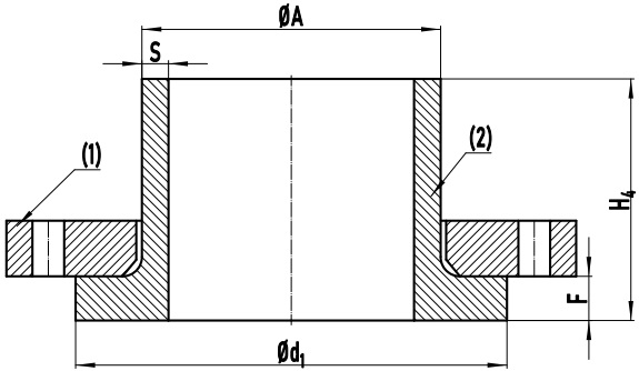
Figure-1: Drawing of the assembly of EN 1092-1 Type 35 and Type 02. (1) Type 02 loose plate flange; (2) Type 35 weld ring neck; Φd1: joint facing diameter; ΦA: outside diameter of neck; F: collar thickness; H4: length through hub; S: wall thickness.
The EN 1092-1 Type 35 weld ring neck is a collar, that is always used with a Type 02 loose plate flange. As illustrated in Figure-1, it consists of the straight pipe length (“neck”) and a flared pipe end (“ring”). The thickness of the flared section is thicker than that of a Type 36 counterpart. It can be viewed as a lap joint stub end with reinforced shoulder thickness. In such a flange assembly, its “neck” end is joined to the pipe by welding, while the loose plate flange mounts to the back surface of the “ring” shoulder, pressing it against the gasket to form a tight seal. EN 1092-1 Type 35 weld neck rings are available in p/T ratings of PN 2.5, PN 6, PN10, PN 16, PN 25 and PN 40. Generally, the Type 35 weld ring neck collar shall be manufactured by a forging process or by welding a ring plate to a seamless pipe. It may be made out of austenitic stainless steels (such as 1.4307/ 304L, 1.4404/ 316L, 1.4571/ 316Ti, etc.) and duplex stainless steels (such as 1.4462/ S32205, 1.4410/ S32750, etc.).
| EN 1092-1 Loose Plate Flanges & Collars | |||
|---|---|---|---|
| Type 02 | Type 04 | Type 32 | Type 33 |
| Type 34 | Type 35 | Type 36 | Type 37 |
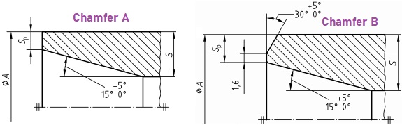
Figure-2: The two types of welding ends for Type 35 weld ring neck: Chamfer A and Chamfer B.
EN 1092-1 Type 35 weld ring neck may be furnished with two types of welding ends, either Chamfer A or Chamfer B, as illustrated in Figure-2. The values of wall thickness (S, Sp) and outside diameter of neck are presented in the two tables below. For sizes highlighted in light green, Chamfer A shall be furnished; For others, Chamfer B shall be furnished.
| ΦA | S for PN 2.5 mm | Sp for PN 2.5 mm | S for PN 6 mm | Sp for PN 6 mm | S for PN 10 mm | Sp for PN 10 mm |
|---|---|---|---|---|---|---|
| 17.2 | 3 | 2 | 3 | 2 | 3 | 2 |
| 21.3 | 3 | 2 | 3 | 2 | 3 | 2 |
| 26.9 | 3 | 2 | 3 | 2 | 3 | 2 |
| 33.7 | 3 | 2 | 3 | 2 | 3 | 2 |
| 42.4 | 3 | 2 | 3 | 2 | 3 | 2 |
| 48.3 | 3 | 2 | 3 | 2 | 3 | 2 |
| 60.3 | 3 | 2 | 3 | 2 | 3 | 2 |
| 76.1 | 4 | 2 | 4 | 2 | 4 | 2 |
| 88.9 | 4 | 2 | 4 | 2 | 4 | 2 |
| 114.3 | 4 | 2 | 4 | 2 | 4 | 2 |
| 139.7 | 5 | 2 | 5 | 2 | 5 | 2 |
| 168.3 | 6 | 2 | 6 | 2 | 6 | 2 |
| 219.1 | 6 | 2.6 | 6 | 2.6 | 6 | 2.6 |
| 273 | 8 | 3.2 | 8 | 3.2 | 8 | 3.2 |
| 323.9 | 8 | 3.2 | 8 | 3.2 | 8 | 3.2 |
| 355.6 | 8 | 3.2 | 8 | 3.2 | 8 | 3.2 |
| 406.4 | 8 | 3.2 | 8 | 3.2 | 8 | 3.2 |
| 457 | 8 | 3.6 | 8 | 3.6 | 8 | 3.6 |
| 508 | 8 | 4 | 8 | 4 | 8 | 4 |
| 610 | 8 | 5 | 8 | 5 | 10 | 5 |
| 711 | 8 | 5 | 8 | 5 | 10 | 6.3 |
| 813 | 10 | 6.3 | 10 | 6.3 | 12 | 6.3 |
| 914 | 10 | 6.3 | 10 | 6.3 | 12 | 8 |
| 1016 | 12 | 8 | 12 | 8 | 12 | 8 |
| 1219 | 14 | 10 | 14 | 10 | 16 | 10 |
| ΦA | S for PN 16 mm | Sp for PN 16 mm | S for PN 25 mm | Sp for PN 25 mm | S for PN 40 mm | Sp for PN 40 mm |
|---|---|---|---|---|---|---|
| 17.2 | 3 | 2 | 3 | 2 | 3 | 2 |
| 21.3 | 3 | 2 | 3 | 2 | 3 | 2 |
| 26.9 | 3 | 2 | 3 | 2 | 3 | 2 |
| 33.7 | 3 | 2 | 3 | 2 | 3 | 2 |
| 42.4 | 3 | 2 | 3 | 2 | 3 | 2 |
| 48.3 | 3 | 2 | 3 | 2 | 3 | 2 |
| 60.3 | 3 | 2 | 4 | 2.6 | 4 | 2.6 |
| 76.1 | 4 | 2 | 5 | 2.6 | 5 | 2.6 |
| 88.9 | 4 | 2 | 6 | 2.6 | 6 | 2.6 |
| 114.3 | 4 | 2 | 6 | 3.2 | 6 | 3.2 |
| 139.7 | 5 | 2 | 6 | 3.2 | 6 | 3.2 |
| 168.3 | 6 | 2 | 8 | 3.2 | 8 | 4 |
| 219.1 | 6 | 2.6 | 8 | 3.2 | 10 | 5 |
| 273 | 8 | 3.2 | 10 | 5 | 12 | 6.3 |
| 323.9 | 10 | 4 | 10 | 6.3 | 12 | 8 |
| 355.6 | 10 | 4 | 12 | 6.3 | 14 | 8 |
| 406.4 | 12 | 5 | 14 | 8 | 16 | 10 |
| 457 | 12 | 5 | 15 | 8 | - | - |
| 508 | 12 | 6.3 | 16 | 10 | - | - |
| 610 | 12 | 8 | 18 | 10 | - | - |
| 711 | 14 | 8 | 20 | 14.2 | - | - |
| 813 | 16 | 10 | 20 | 14.2 | - | - |
| 914 | 18 | 10 | - | - | - | - |
| 1016 | 18 | 10 | - | - | - | - |
Surface finishes for Type 35: (1) surface finishes for outside diameter: Ra ≤ 25μm, Rz ≤ 160μm; (2) surface finishes for center bore diameter: Ra ≤ 25μm, Rz ≤ 160μm; (3) surface finishes for jointing faces: 3.2μm ≤ Ra ≤ 12.5μm, 12.5μm ≤ Ra ≤ 50μm. The jointing faces shall be machined by a turning process.
| DN | F | H4 | d1 | Mass |
|---|---|---|---|---|
| 10 | 5 | 28 | 35 | 0.08 |
| 15 | 5 | 30 | 40 | 0.09 |
| 20 | 6 | 32 | 50 | 0.17 |
| 25 | 7 | 35 | 60 | 0.26 |
| 32 | 8 | 35 | 70 | 0.36 |
| 40 | 8 | 38 | 80 | 0.45 |
| 50 | 8 | 38 | 90 | 0.53 |
| 65 | 8 | 38 | 110 | 0.70 |
| 80 | 10 | 42 | 128 | 1.0 |
| 100 | 10 | 45 | 148 | 1.3 |
| 125 | 10 | 48 | 178 | 1.9 |
| 150 | 10 | 48 | 202 | 2.4 |
| 200 | 11 | 55 | 258 | 3.9 |
| 250 | 12 | 60 | 312 | 5.8 |
| 300 | 12 | 62 | 365 | 6.8 |
| 350 | 13 | 62 | 415 | 9.5 |
| 400 | 14 | 65 | 465 | 11.6 |
| 450 | 15 | 65 | 520 | 15.0 |
| 500 | 16 | 68 | 570 | 15.9 |
| 600 | 16 | 70 | 670 | 23.0 |
| 700 | 16 | 70 | 775 | 30.9 |
| 800 | 16 | 70 | 880 | 41.5 |
| 900 | 16 | 70 | 980 | 50.0 |
| 1000 | 18 | 70 | 1080 | 58.9 |
| 1200 | 20 | 90 | 1280 | 56.3 |
| DN | F | H4 | d1 | Mass |
|---|---|---|---|---|
| 10 | 5 | 28 | 35 | 0.08 |
| 15 | 5 | 30 | 40 | 0.09 |
| 20 | 6 | 32 | 50 | 0.17 |
| 25 | 7 | 35 | 60 | 0.26 |
| 32 | 8 | 35 | 70 | 0.36 |
| 40 | 8 | 38 | 80 | 0.45 |
| 50 | 8 | 38 | 90 | 0.53 |
| 65 | 8 | 38 | 110 | 0.70 |
| 80 | 10 | 42 | 128 | 1.0 |
| 100 | 10 | 45 | 148 | 1.3 |
| 125 | 10 | 48 | 178 | 1.9 |
| 150 | 10 | 48 | 202 | 2.4 |
| 200 | 11 | 55 | 258 | 3.9 |
| 250 | 12 | 60 | 312 | 5.8 |
| 300 | 12 | 62 | 365 | 6.8 |
| 350 | 13 | 62 | 415 | 9.5 |
| 400 | 14 | 65 | 465 | 11.6 |
| 450 | 15 | 72 | 520 | 15.0 |
| 500 | 16 | 75 | 570 | 15.9 |
| 600 | 16 | 70 | 670 | 23.0 |
| 700 | 16 | 70 | 775 | 30.9 |
| 800 | 16 | 70 | 880 | 41.5 |
| 900 | 16 | 70 | 980 | 50.0 |
| 1000 | 18 | 70 | 1080 | 58.9 |
| 1200 | 20 | 90 | 1295 | 93.2 |
| DN | F | H4 | d1 | Mass |
|---|---|---|---|---|
| 10 | 5 | 35 | 40 | 0.08 |
| 15 | 5 | 38 | 45 | 0.09 |
| 20 | 6 | 40 | 58 | 0.17 |
| 25 | 7 | 40 | 68 | 0.26 |
| 32 | 8 | 42 | 78 | 0.36 |
| 40 | 8 | 45 | 88 | 0.45 |
| 50 | 8 | 45 | 102 | 0.53 |
| 65 | 8 | 45 | 122 | 0.70 |
| 80 | 10 | 50 | 138 | 1.0 |
| 100 | 10 | 52 | 158 | 1.3 |
| 125 | 10 | 55 | 188 | 1.9 |
| 150 | 10 | 55 | 212 | 2.4 |
| 200 | 11 | 62 | 268 | 3.9 |
| 250 | 12 | 68 | 320 | 5.8 |
| 300 | 12 | 68 | 370 | 6.8 |
| 350 | 13 | 68 | 430 | 9.5 |
| 400 | 14 | 72 | 482 | 11.6 |
| 450 | 15 | 72 | 532 | 15.0 |
| 500 | 16 | 75 | 585 | 15.9 |
| 600 | 18 | 80 | 685 | 23.0 |
| 700 | 20 | 80 | 800 | 30.9 |
| 800 | 20 | 90 | 905 | 41.5 |
| 900 | 22 | 95 | 1005 | 50.0 |
| 1000 | 24 | 95 | 1110 | 58.9 |
| 1200 | 26 | 115 | 1330 | 93.2 |
| DN | F | H4 | d1 | Mass |
|---|---|---|---|---|
| 10 | 5 | 35 | 40 | 0.08 |
| 15 | 5 | 38 | 45 | 0.09 |
| 20 | 6 | 40 | 58 | 0.17 |
| 25 | 7 | 40 | 68 | 0.26 |
| 32 | 8 | 42 | 78 | 0.36 |
| 40 | 8 | 45 | 88 | 0.45 |
| 50 | 8 | 45 | 102 | 0.53 |
| 65 | 8 | 45 | 122 | 0.70 |
| 80 | 10 | 50 | 138 | 1.0 |
| 100 | 10 | 52 | 158 | 1.3 |
| 125 | 10 | 55 | 188 | 1.9 |
| 150 | 10 | 55 | 212 | 2.4 |
| 200 | 11 | 62 | 268 | 3.9 |
| 250 | 12 | 70 | 320 | 5.8 |
| 300 | 14 | 78 | 378 | 9.5 |
| 350 | 18 | 82 | 438 | 15.2 |
| 400 | 20 | 85 | 490 | 18.7 |
| 450 | 22 | 87 | 550 | 24.4 |
| 500 | 22 | 90 | 610 | 29.1 |
| 600 | 24 | 95 | 725 | 40.3 |
| 700 | 26 | 100 | 795 | 45.2 |
| 800 | 28 | 105 | 900 | 59.9 |
| 900 | 30 | 110 | 1000 | 75.6 |
| 1000 | 35 | 120 | 1115 | 106.46 |
| DN | F | H4 | d1 | Mass |
|---|---|---|---|---|
| 10 | 5 | 35 | 40 | 0.08 |
| 15 | 5 | 38 | 45 | 0.09 |
| 20 | 6 | 40 | 58 | 0.17 |
| 25 | 7 | 40 | 68 | 0.26 |
| 32 | 8 | 42 | 78 | 0.36 |
| 40 | 8 | 45 | 88 | 0.45 |
| 50 | 10 | 48 | 102 | 0.69 |
| 65 | 11 | 52 | 122 | 1.1 |
| 80 | 12 | 58 | 138 | 1.6 |
| 100 | 14 | 65 | 162 | 2.4 |
| 125 | 16 | 68 | 188 | 3.2 |
| 150 | 18 | 75 | 218 | 4.6 |
| 200 | 18 | 80 | 278 | 6.6 |
| 250 | 18 | 88 | 335 | 10.0 |
| 300 | 20 | 92 | 395 | 15.3 |
| 350 | 22 | 100 | 450 | 20.8 |
| 400 | 24 | 110 | 505 | 28.6 |
| 450 | 26 | 110 | 615 | 34.4 |
| 500 | 28 | 125 | 720 | 45.8 |
| 600 | 30 | 125 | 820 | 61.0 |
| 700 | 30 | 125 | 930 | 73.0 |
| 800 | 35 | 135 | 1030 | 97.0 |
| DN | F | H4 | d1 | Mass |
|---|---|---|---|---|
| 10 | 5 | 35 | 40 | 0.08 |
| 15 | 5 | 38 | 45 | 0.09 |
| 20 | 6 | 40 | 58 | 0.17 |
| 25 | 7 | 40 | 68 | 0.26 |
| 32 | 8 | 42 | 78 | 0.36 |
| 40 | 8 | 45 | 88 | 0.45 |
| 50 | 10 | 48 | 102 | 0.69 |
| 65 | 11 | 52 | 122 | 1.1 |
| 80 | 12 | 58 | 138 | 1.6 |
| 100 | 14 | 65 | 162 | 2.4 |
| 125 | 16 | 68 | 188 | 3.2 |
| 150 | 18 | 75 | 218 | 4.6 |
| 200 | 20 | 88 | 285 | 8.8 |
| 250 | 22 | 105 | 345 | 14.4 |
| 300 | 25 | 115 | 410 | 20.7 |
| 350 | 28 | 125 | 465 | 30.7 |
| 400 | 32 | 135 | 535 | 45.4 |
Tolerances: (1) ΦA: for size ≤ DN150, ±0.75% & min. ±0.3mm; for size > DN150, ±1% & max. ±3.0mm. (2) S: for S ≤ 8mm, (+15%, -10%); for S > 8mm, (+15%, -5%). (3) Sp: for S ≤ 6mm, (+1.0mm, 0mm); for S > 6mm, (+2.0mm, 0mm). (4) H4: for size ≤DN80, ±1.5mm; for DN80 < size ≤ DN250, ±2.0; for size > DN 250, ±3.0mm. (5)F: for F ≤ 18mm, ±1.0mm; for F > 18mm, ±1.5mm. (6) d1: for size ≤ DN250, (+2.0mm, -1.0mm); for size > DN250, (+3.0mm, -1.0mm).