Categories
- Pipe & Tube (18)
- Flange & Fitting (97)
- Fastener & Gasket (12)
- Valve & Pump (18)
- Base Material (11)
- Equipment (9)
- Application (31)
- Technical (110)
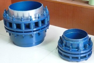
Rotary expansion joints
Rotary expansion joints, also known as rotary compensators, originate from slip type expansion joints. Generally, as illustrated in Figures 1-1 & 1-2, they are constructed by a set of components including (1) rotary sleeve, (2) packing & packing gland, (3) body sleeve, (4) anti-blowout retainer, (5) bolting, (6) butt-welding end connection.
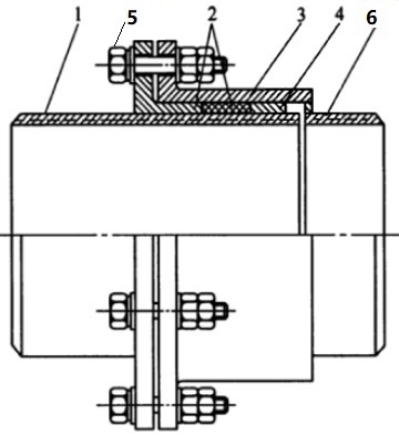
Figure 1-1: drawing of a typical straight-type rotary expansion joint.
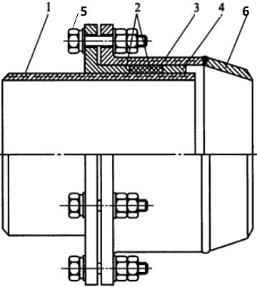
Figure 1-2: drawing of a typical reducing-type rotary expansion joint.
The rotary sleeve can rotate freely along its longitudinal axis. The packing is stuffed in the space between the rotary sleeve and the body, tightened by the retainer, gland flange and its bolting. Springs may be incorporated into the bolting to ensure a tight loading. The rotary expansion joints can be simply classified as straight type or reducing type according to how its butt welding end transitions to the piping diameter from body diameter. Rotary expansion joints supplied by Shijiazhuang Metalsin have the following advantages: maintenance-free with a 6-year warranty, no pressure thrust, no water hammer, self-pressurized sealing.
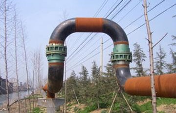
A pair of rotary expansion joints used in piping application.
At least two rotary expansion joints shall be used together in the same piping section to absorb the thermal expansion or angular rotation. They shall be arranged in “Π-style” or “Ω-style” piping layout. Take “Π-style” layout for example, a pair of rotary expansion joints shall be installed parallel in piping in a vertical plane, while the main piping is deployed in the horizontal plane. When thermal expansion of the piping is initiated, two parallel forces in opposite directions formed a couple through the arm of force “L”. As illustrated in Figure 2-1, the couple makes L to rotate around Z axis to absorb the thermal expansion. The function in the Ω-style arrangement is more complicated and 3 sets of rotary expansion joints shall be incorporated.
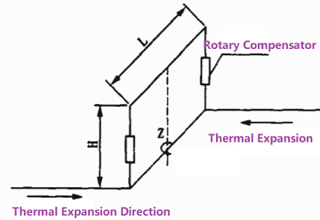
Figure 2-1: Π-style layout of rotary expansion joints in piping.
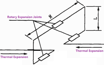
Figure 2-1: Ω-style layout of rotary expansion joints in piping.
Rotary expansion joints are usually deployed in overhead pipe racks. They are widely used in hot water and steam applications, chemical & pharmaceutical industries, pulp and paper industry, as well as petroleum refinery.
The body sleeve, rotary sleeve, retainer, gland flange and the butt welding end connector shall be selected from metallic materials such as carbon steel (ASTM A105, ASTM A106 Gr.B, S235JR, Q235, P235GH), low alloy steel (ASTM A335 P11, P22, P5, 16Mo3, 15CrMo, 12Cr1MoV), stainless steel (SS 304, SS304L, SS 316, SS 316L, SS 317, SS 317L, etc), or nickel alloy (Inconel 625, Monel 400, Hastelloy C-276). The packing material may be flexible graphite, carbon fiber, PTFE, EPDM, NBR, etc. Typical bolting materials include ASTM A193 B7 / ASTM A194 2H, ASTM A193 B8, B8M/ ASTM A194 8, 8M.
Necessary tests for the rotary expansion joints include non-destructive test (NDT), pressure proof test, sealing test, torque test, fatigue test, dimensional examination and visual inspection.