Categories
- Pipe & Tube (18)
- Flange & Fitting (97)
- Fastener & Gasket (12)
- Valve & Pump (18)
- Base Material (11)
- Equipment (10)
- Application (31)
- Technical (110)
A line blank can be viewed as an “isolation flange” inserted between two mating flanges to switch on or off the piping system after disassembling certain flange bolting. In many piping systems, line blanks are usually required to isolate individual pieces of equipment at shutdown and to positively blank off selected process lines at the piping unit limits. They are also needed during operation, maintenance, or inspection and testing wherever positive shutoff is required to prevent leakage of one fluid into another. Line blanks are generally manufactured in accordance with ASME B16.48. The standard covers pressure-temperature ratings, materials, dimensions, tolerances, marking, and testing for operating line blanks in sizes NPS 1/2 through NPS 24 for installation between ASME B16.5 flanges in the 150, 300, 600, 900, 1500, and 2500 pressure classes. Besides, line blanks can also be designed in accordance with ASME B31.3.
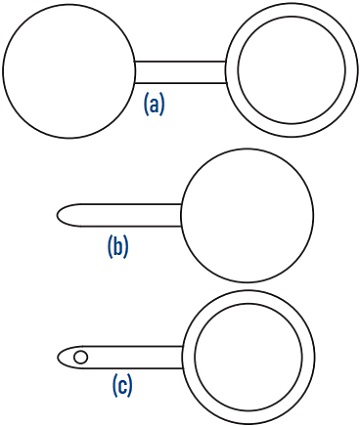
The illustration of 3 different types of line blanks: (a) figure-8 line blank/ spectacle blind, (b) spade flange/ paddle blank, (c) paddle spacer/ ring spacer.
ASME B16.48 has indicated 3 different types of line blanks. The figure-8 blank, also called a spectacle blank, is a pressure-retaining plate with one solid end and one open end connected with a web or tie bar. The solid end (also called the blank) is used to shutdown the line, while the open end (also called the spacer) is used to turn on the line. The paddle blank, also called a spade flange, is similar to the solid end of a figure-8 blank. It has a plain radial handle. The paddle spacer, also called a ring spacer, is similar to the open end of a figure-8 blank. It also has a plain radial handle. The paddle blank is generally used in conjunction with a paddle spacer in large sizes. The use of figure-8 blanks obviously ensures that the companion spacer is on hand when needed (and vice versa). However, these are difficult to handle in the larger sizes [i.e., above NPS 12 (DN 300)], and instead separate spacers and blanks are used.
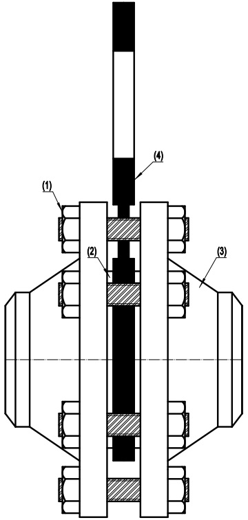
The illustration of the assembly of a spectacle blind flange; (1) bot & nut, (2) gasket, (3) mating flange, (4) spectacle blind flange.
A blind flange is a flange used to close the end of a pipe which has equally spaced bolt holes drilled along the bolt circle. A blank flange is a flange that is not drilled but is otherwise complete. However, the two nomenclatures are equivalent or identical in many practices. That’s why line blanks have many different names:
Line blanks should be located in horizontal lines to ease their installation and removal. They should not be used in vertical water and steam lines in climates where danger of freezing exists. The material of a line blank conforming to ASME B16.48 shall be the same as that of the mating flanges between which the line blank will be inserted. It shall be in accordance with the applicable material specification listed in Table 1A of ASME B16.5. The blank or spacer portion of a line blank shall be manufactured as one piece. However, attachment of the handle or tie bar to a blank or spacer portion by welding or other means is permitted.

A spectacle blind flange assembled in the pipeline, which is on the “open” position.
ASME B16.48 line blanks can be designated in 6 pressure rating classes: 150#, 300#, 600#, 900#, 1500#, and 2500#. The maximum allowable working gauge pressures at elevated temperatures are the same as that of the mating ASME B16.5 flanges. Line blanks may be subjected to system tests at a pressure not to exceed 1.5 times the 38°C (100°F) rating rounded off to the next higher 1 bar (25 psi) increment.
The handle or web (tie bar) may be integral or attached to the blank or spacer. The web and its attachment shall be capable of supporting the weight of the blank or spacer in all orientations without permanent deformation to the web. Handles for paddle blanks shall be solid with no openings. Handles for paddle spacers shall have a single through indicator hole located near the end of the handle. The hole diameter shall not be less than 12.7 mm (1/2″). Surfaces of the line blank’s edge shall be free of projections that would interfere with gasket seating.

A figure-8 blank flange shutdown the pipeline for maintenance.
There are 4 facing types for line blanks manufactured in accordance with ASME B16.48: flat face, raised face, female ring joint, and male ring joint. The gasket seating surface and dimensions for line blanks used with raised face flanges shall be in accordance with ASME B16.5. The height of the raised face shall be in addition to the thickness of the line blank. A flat face can be obtained by the removal of the raised face. Female ring-joint grooves shall be shaped with the groove side wall surface finish not exceeding 1.6 m (63 in.) Ra roughness. The gasket shape (ring) for male ring-joint blanks shall not exceed 1.6 m (63 in.) Ra roughness.
| ASME B16.48 Line Blanks | |||
|---|---|---|---|
| Figure-8 | FF/RF | F/RTJ | M/RTJ |
| Spade | FF/RF | F/RTJ | M/RTJ |
| Spacer | FF/RF | F/RTJ | M/RTJ |
For NPS 1/2, NPS 3/4, and NPS 1 blanks in all raised face classes, the inside diameter is equal to standard weight welding neck flange bore. For NPS 1-1/4 and larger blanks in classes 150 and 300 raised face, the inside diameter is equal to the pipe outside diameter. For NPS 1-1/4 and larger blanks in classes 600 and 900 raised face, the inside diameter is equal to SCH 10S welding neck flange bore. For class 1500 raised face blanks, the inside diameter is equal to SCH 40 welding neck flange bore. For class 2500 raised face blanks, the inside diameter is equal to SCH 40 through NPS 6, SCH 60 for NPS 8 and NPS 10, and SCH 80 for NPS 12. For all ring-joint blanks, the inside diameter is equal to the pipe outside diameter.
Tolerances for facings and facing finishes shall be in accordance with ASME B16.5. Thickness tolerances for the line blanks are (+3.0 mm, -0.0 mm) for NPS ≤ 18 and (+4.8 mm, -0.0 mm) for NPS ≥ 20.