Categories
- Pipe & Tube (18)
- Flange & Fitting (97)
- Fastener & Gasket (12)
- Valve & Pump (18)
- Base Material (11)
- Equipment (9)
- Application (31)
- Technical (110)
The AWWA C207 is an American National Standard for steel pipe flanges for waterworks service, sizes 4″ through 144″ (100 mm through 3600 mm). The AWWA is the abbreviation of “American Water Works Association”. The origin of AWWA C207 can be dated back to year 1942 when a paper proposing standards for slip-on steel-ring flanges for welding to steel water pipes. This standard was necessary because the lowest pressure ratings for steel flanges at that time were those having cold-water pressure ratings of 275 psi (1896 KPa). The ratings are far higher than those ordinarily needed for water service (150 psi / 1034 KPa) primary pressure rating.
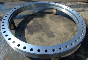
AWWA C207 Class B (86 psi) steel-ring flanges, 60″ flat face (FF).
The AWWA C207 flanges are intended for attachment to steel pipes, fittings, valves or other appurtenances in water utility service. The standard has specified two general types of flange: (1) ring-type slip-on flanges, also known as ring flanges or plate flanges; (2) blind flanges. Both the ring flange and blind flange are steel flanges without hub. Besides, in Appendix B, it also provides additional information for dimensions of steel-hub flanges. The AWWA C207 flange can be further classified into four classes according to its working pressure limit: Class B (86 psi), Class D (175-150 psi), Class E (275 psi), Class F (300 psi). The pressure limits are for conditions and temperatures customary in water utility service.
| AWWA C207 Pipe Flange Dimensions & Masses |
|
|---|---|
| Ring Flange | Class B | Class D Class E | Class F |
| Blind Flange | Class B | Class D Class E | Class F |
| Hub Flange | Class D | Class E |
The AWWA C207 steel pipe flanges shall be made from materials complying with the requirements of the Safe Drinking Water Act. Basically, the AWWA C207 flange shall be made from steel plate, bar or forgings conforming to the following requirements: (1) Specified minimum tensile strength = 50,000 psi [345 MPa]; (2) Specified minimum yield strength = 32,000 psi [221 MPa]; (3) Elongation, 2″ [50 mm] gauge length (minimum) = 18%, or 8″ [200 mm] gauge length (minimum) = 14%; (4) Carbon (maximum) = 0.35%; (5) Phosphorus (maximum) = 0.04%; (6) Sulfur (maximum) = 0.05%. The AWWA C207 flanges shall be furnished with bolts & studs made to ASTM A193 B7 and ASTM A194 2H heavy hex nuts or ASTM A563 heavy hex nuts for 1″ and smaller. Washers, when used, shall meet the requirements of ASTM F436. The flange gasket shall be furnished in full face type or ring type, made from rubber, compressed fiber, or PTFE, respectively.
Referring to manufacturing methods, AWWA C207 steel flanges may be made from seamless forgings, cut from plate as a single piece, welded bar rings, or segmented and welded plates. Small & medium size flanges are usually manufactured integrally by a forging or integral cutting process. When the O.D of a flange exceeds the width of available plate material (approx. 78″ [1950 mm] ID and larger), it shall be manufactured by welding maximum four segments and all welds shall be 100% X-ray inspected.
Inside diameter of flange: +1/16″ [1.6 mm], -0; Outside diameter of flange: ±1/8″ [3.2 mm]; Thickness of flange 18″ [450 mm] and smaller: +1/8″ [3.2 mm], -0; Thickness of flange 20″ [500 mm] and larger: +3/16″ [4.8 mm], -0; Bolt circle diameter: ±1/16″ [1.6 mm]; Bolt hole spacing: ±1/32 [0.79 mm].
AWWA C207 flanges of all classes and types shall be flat faced (FF) – that is without projection or raised face. Either a serrated concentric or serrated spiral finish having 24~55 grooves per inch (0.94~2.17 grooves per mm) shall be used. The cutting tool employed shall have a radius of 0.06 inch (1.52 mm) or larger. The resultant surface finish shall have a 125 to 500 μinch (3.2 to 12.7 μm) roughness average (Ra), as defined in B46.1. Flange faces shall be free of lining and coating materials, except that a removable corrosion inhibitor is permitted until installation. The gasket seating surface shall not have protrusions.
For flanges up to 84″ (2,100 mm) in diameter, bolt holes shall be drilled 1/8″ (3.2 mm) larger in diameter than the nominal diameter of the bolt. For flanges larger than 84″ (2,100 mm) in diameter, bolt holes shall be drilled 3/16″ (4.8 mm) larger than the nominal bolt diameter. Bolt holes may be over-sized by an additional 1/8″ (3.2 mm) to accommodate insulators or to facilitate alignment with the mating flange. If bolt holes are over-sized, washers shall be used.
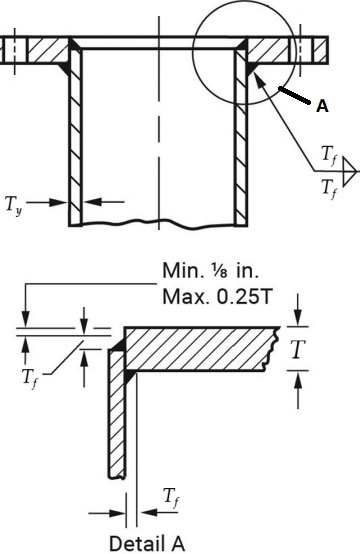
Figure-1: the welding attachment of AWWA C207 steel pipe flange to mating pipe. Tf: fillet weld size; Ty: pipe wall thickness; T: flange thickness.
AWWA C207 steel pipe flanges shall be attached to pipes, fittings, or other appurtenances by means of two filler welds as shown in Figure-1. For pipe wall thicknesses, Ty, 1/4″ (6.4 mm) or less, the fillet size, Tf, shall be equal to Ty. For pipe wall thicknesses greater than 1/4″ (6.4 mm), the fillet weld size, Tf, may be reduced to the calculated thickness of the attached steel pipe or 1/4″ (6.4 mm), whichever is greater. When the weld root opening is greater than 1/16″ (1.6 mm), increase the weld size according to the root opening. Root openings shall not exceed 3/16″ (4.8 mm). The welding procedure, welder and welding operator qualification shall be based on an applicable welding code, such as AWS D1.1/ D1.1M or ASME Boiler and Pressure Vessel Code, Section IX.
Flanges shall be stenciled with the size, material and trademark, as well as with the AWWA class and heat number. For example: M 48″ AWWA C207 Class D ASTM A516 Gr.60 6558. Protective coating shall be furnished conforming to either AWWA C203, C209, C210, C213, C216, C217, C218, or C222. Generally, the flange-coating alternatives include yellow golden, black, anti-rust oil, PE, and coal tar, etc.