Categories
- Pipe & Tube (18)
- Flange & Fitting (97)
- Fastener & Gasket (12)
- Valve & Pump (18)
- Base Material (11)
- Equipment (10)
- Application (31)
- Technical (110)
Shijiazhuang Metalsin supplies lap joint flanges conforming to ASME B16.5 in Class 150 through Class 2500 covering a comprehensive range of steel and alloy steel materials. Attachment of the lap joint flange to the piping system requires a lap-joint stub end. The stub end can be viewed as a length of pipe sleeve with one end butt welded and the other end flared at right angle to the pipe axis. The lap-joint flange and stub end compose a two-piece composite lap joint connection.
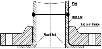
Figure-1: the lapped joint connection is composed of a lap joint flange and a stub end.
In this lapped connection, prior to the “pipe sleeve” being welded to the adjoining pipe, the loose-type lap joint flange slip over the straight length of the pipe sleeve and abuts against the back face of the stub end or its “flared shoulder”. It is free to spin the flange for proper alignment of bolt holes, which is used to bolt the joint together subsequently. The lap joint flange is also known as a lapped “backing flange” and the flared end is also called as “lap” of the stub end.
Lap joint flanges shall be furnished with flat faces and the lower corner of the bore shall be furnished with a rounded transition. As illustrated in Figure-1, the flared end of the stub end protrudes from the flange and acts as a raised face. In fact, the diameter of the flared end is the same as that of a raised face of a conventional slip on flange. The lap joint facing depends on the lap of the stub end. In addition to raised face, it may be furnished with ring joint facing, large male and female facing, tongue and groove facing. The thickness of the lap remaining after machining the facing shall be no less than the nominal wall thickness of pipe used. The outside diameter of the lap shall be same as that of the facing dimensions stipulated by ASME B16.5.
Due to the composite two-piece configuration, the lap joint flange obtains two obvious advantages in use. Imagine a lapped joint piping connection in which an expensive alloy (nickel, zirconium, tantalum, or titanium, etc) is required for all “wetted” parts to resist corrosion. The stub end can be made from the corrosion-resistant but expensive alloy and the lap joint flange functioning as a backing flange may be made from common carbon steels. This is more cost-effective than a complete alloy flange. On the other hand, since the lap joint flange itself is not welded to the pipe, it may rotate to align bolt holes readily and the assembly and disassembly are much easier. This facilitates the operation of a piping system that requires frequent dismantling for inspection or routine maintenance.
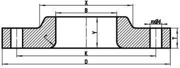
Firgure-2: a typical drawing for the lap joint flange conforming to ASME B16.5
There are also some disadvantages for using lap joint flanges. The crevices formed between the internal surface of flange bore and the external surface of the stub ends may collect contaminates readily. And the collected contaminates could present a problem and result in crevice corrosion. The longitudinal stresses, resulting from pressure, weight, and thermal expansion, may accumulate and exceed the basic allowable stress at the design temperature stipulated by ASME B31.3. Hence the lap joint flange is generally used in mild service, when the loads applied by the pipe to the flange connection are small. Since the lap joint flange may be of a material different from that of the stub end, possible galvanic corrosion may be incurred in some situations.
| ASME B16.5 Lap Joint Flanges, Classes | |||
|---|---|---|---|
| 150# | 300# | 400# | 600# |
| 900# | 1500# | 2500# | - |
The dimensions of the ASME B16.5 lap joint flange are illustrated in Figure-2: D – outside diameter of flange, Y – length through hub, B – minimum bore diameter, X – diameter of hub, T – minimum flange thickness, r – corner bore radius of lapped flange and pipe, n – number of bolts, d – diameter of bolt hole. The tolerances of lapped joint flange are the same as that of slip on flanges.