Categories
- Pipe & Tube (18)
- Flange & Fitting (97)
- Fastener & Gasket (12)
- Valve & Pump (18)
- Base Material (11)
- Equipment (9)
- Application (31)
- Technical (110)
The slip on flange (S/O flange) manufactured in accordance with ASME B16.5 is a loose-type flange which has no direct connection to the adjoining pipe wall or the nozzle neck, or the vessel. It has a low hub that allows the flange to slip onto the pipe prior to welding. Two fillet welds, one internal and one external, shall be applied to provide sufficient strength and prevent leakage. It requires less skill to assemble and permits aligning bolt holes by rotating the flange before welding.
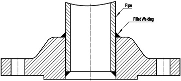
Illustration of welding a pipe to a slip-on flange conforming to ASME B16.5: two fillet welds shall be furnished.
The slip on flange is shorter in length than a weld neck flange, and is used in areas where short tie-ins are necessary or space limitations necessitate its use. Generally, the life span of a slip-on flange connection is about one-third that of the weld neck flange. Despite of additional welding involved during installation, its lower initial cost makes the s/o flange preferred over w/n flanges by many users. It is generally used in non-corrosive, non-critical, moderate pressure services. Slip on flanges of Class 150 and Class 300 are most commonly seen in utility engineering.
Similar to welding neck flange, the slip on flange conforming to ASME B16.5 may generally be furnished with three facing types: raised face (RF), flat face/ full face (FF), or ring type joint (RTJ). As a flange with hub, it shall be manufactured as one piece in accordance with the applicable material specification, either from forgings or castings.
According to ASME B16.5, slip on flanges are available in six pressure ratings covering Class 150, Class 300, Class 400, Class 600, Class 900 and Class 1500 from 1/2″ to 24″, except that slip on flanges of Class 1500 are only available through 1/2″ to 2-1/2″.
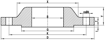
A typical drawing of slip on flange conforming to ASME B16.5 with raised face.
As illustrated in the drawing, D: outside diameter of flange, K: diameter of bolt circle, G: diameter of raised face, B: bore diameter of slip on flange, X: diameter of hub at the large end of hub, n: number of bolt holes, d: diameter of bolt hole, Y: length through hub, T: minimum thickness of flange, t: height of raised face.
| Item | Condition | Tolerance |
|---|---|---|
| D | D ≤ 24" | ±1.5 |
| D > 24" | ±3.0 | |
| B | NPS ≤ 10 | +1.0 -0.0 |
| NPS ≥ 12 | +1.5 -0.0 |
|
| K | NPS ≤ 24 | ±1.5 |
| G | 2 mm RF | ±1.0 |
| 7 mm RF | ±0.5 | |
| X | NPS ≤ 5 | +2.0 -1.0 |
| NPS ≥ 6 | +4.0 -1.0 |
|
| Y | NPS ≤ 10 | ±2.0 |
| NPS ≥ 12 | ±3.0 | |
| T | NPS ≤ 18 | +3.0 -1.0 |
| NPS ≥ 20 | +5.0 -0.0 |
|
| *BCC | NPS ≤ 2-1∕2 | 0.8 |
| NPS ≥ 3 | 1.5 | |
| *BHS | NPS ≤ 24 | ±0.8 |
| ASME B16.5 SO Flanges: Dimensions & Weights | ||
|---|---|---|
| Class150 | Class300 | Class400 |
| Class600 | Class900 | Class1500 |