Categories
- Pipe & Tube (18)
- Flange & Fitting (97)
- Fastener & Gasket (12)
- Valve & Pump (18)
- Base Material (11)
- Equipment (8)
- Application (30)
- Technical (110)
The welding neck flange (WN) conforming to ASME B16.5 is a typical integral-type flange. It is cast or forged integrally with the tapered neck which is butt welded to the pipe. This design provides a smooth transition with little stress concentration since the high-stress concentration at the base of the flange is reduced by transferring stress to the adjoining pipe. There are no gaps or recesses that could lead to crevice corrosion. The tapered neck is also known as “nozzle neck”, or more commonly as “high hub”. Although expensive, the welding neck flange is the best designed butt weld flange available since the long tapered hub provides superior strength and resistance to dishing.

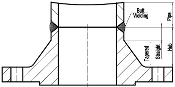
The butt welding of a weld neck flange to adjoining pipe.
According to ASME B16.5, the hub of the welding neck flange can be roughly divided into a tapered portion and a straight length. The straight length of 6 mm is machined to precisely match with the adjoining pipe so that the welding can be done conveniently. Weld neck flanges are bored to match the inside diameter of the adjoining pipe. The thinner the wall of the pipe, the larger the bore through the flange. The thicker the wall of the pipe, the smaller the bore. Because of these matching relationship, there is no restriction to the flow. Turbulence and erosion are therefore eliminated.
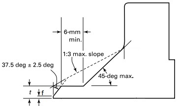
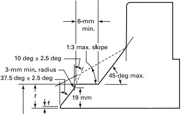
The ASME B16.5 welding neck flange shall be furnished with cut square end when wall thickness is less than 5 mm, plain bevel end when wall thickness is from 5 mm to 22 mm inclusive, or compound bevel end when wall thickness is greater than 22 mm. The butt welding ends shall be machined in accordance with the requirements of ASME B16.25. The dimensions and tolerances of plain bevel and compound bevel are illustrated in below two drawings. In particular, the wall thickness t shall conforming to the adjoining pipe’s wall thickness requirement; a root face in width f of 2 mm shall be machined at the top of the bevel with tolerance of ±1 mm.

Drawing of plain bevel end of ASME B16.5 WN flange

Compound bevel end of ASME B16.5 welding neck flange.
Three most common facing types are available including flat face (FF), raised face (RF), and ring joint face (RTJ). Welding neck flanges are normally used in severe service applications involving high pressures, high temperatures, large external loads or cryogenic conditions.
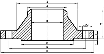
Weld neck flanges conforming to ASME B16.5 can be classified into 7 pressure ratings from Class 150 to Class 2500. A typical drawing is presented below in which each dimension is marked with a symbol letter: D – outside diameter of flange, K – bolt circle diameter, G – raised face diameter, B – bore diameter of flange, A: diameter of hub at welding point / outside diameter of pipe, X – diameter of hub at base, T – minimum flange thickness, Y- length through hub, t – raised face height, n – number of bolts, d – diameter of bolt hole.

A typical drawing for ASME B16.5 welding neck flange, RF.
| Dimension | Condition | Tolerance |
|---|---|---|
| D | D ≤ 610 mm | ±1.5 |
| D > 610 mm | ±3.0 | |
| K | NPS ≤ 24 | ±1.5 |
| G | 2 mm RF | ±1.0 |
| 7 mm RF | ±0.5 | |
| B | NPS ≤ 10 | ±1.0 |
| 12 ≤ NPS ≤ 18 | ±1.5 | |
| NPS ≥ 20 | +3.0, -1.5 | |
| A | NPS ≤ 5 | +2.0, -1.0 |
| NPS ≥ 6 | +4.0, -1.0 | |
| X | X ≤ 610 mm | ±1.5 |
| X > 610 mm | ±3.0 | |
| Y | NPS ≤ 4 | ±1.5 |
| 5 ≤ NPS ≤ 10 | +1.5, -3.0 | |
| NPS ≥ 12 | +3.0, -5.0 | |
| T | NPS ≤ 18 | +3.0, -0.0 |
| NPS ≥ 20 | +5.0, -0.0 | |
| *BCC | NPS ≤ 2-1∕2 | 0.8 |
| NPS ≥ 3 | 1.5 | |
| *BHS | NPS ≤ 24 | ±0.8 |
| ASME B16.5 WN Flanges: Dimensions & Weights | |||
|---|---|---|---|
| Class150 | Class 300 | Class 400 | Class 600 |
| Class 900 | Class 1500 | Class 2500 | - |
