Categories
- Pipe & Tube (18)
- Flange & Fitting (97)
- Fastener & Gasket (12)
- Valve & Pump (18)
- Base Material (11)
- Equipment (8)
- Application (30)
- Technical (110)

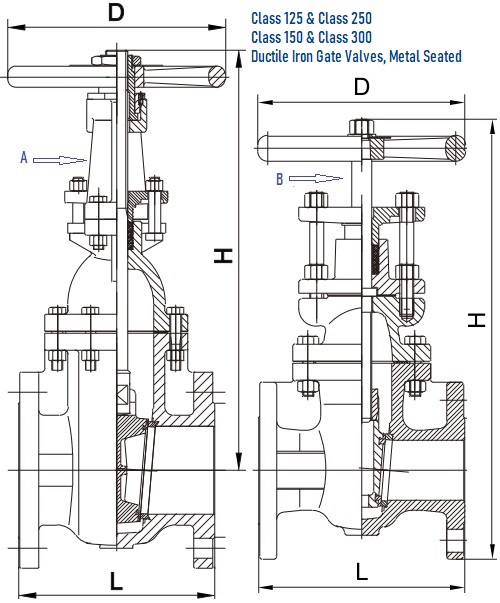
G.A drawings for ductile iron gate valves designed according to MSS SP 128, metal seated, OS&Y rising stem (A) and non-rising stem (B).
Design features of MSS SP 128 ductile iron gate valves: RF flanged end connection; solid wedge (one-piece); OS&Y rising stem or non-rising stem; bolted bonnet; handwheel operated; metal seated (copper alloy seating surfaces); Class 125 and Class 250 gate valve bodies and bonnets shall be either ASTM A536 or ASTM A395 ductile iron and shall have minimum wall thickness as specified in ASME B16.1 for the corresponding Class and NPS fitting; Class 150 and Class 300 gate valve bodies and bonnets shall be ASTM A395 ductile iron and shall have the minimum wall thickness as specified in ASME B16.42 for the corresponding Class and NPS fitting. Sizes available: 2″~24″ for Class 125; 2″~12″ for Class 150, Class 250, and Class 300. Face-to-face dimensions shall be in accordance with ASME B16.10.
| Valve Part | Materials |
|---|---|
| Body | ASTM A536 ASTM A395 |
| Bonnet | ASTM A536 ASTM A395 |
| Disc | ASTM A536 ASTM A395 |
| Seat Ring on Wedge | ASTM B62 C83600 |
| Seat Ring on Body | ASTM B62 C83600 |
| Stem | ASTM B16 C36000 AISI 420 |
| Packing | Graphite |
| Handwheel | ASTM A536 ASTM A395 |
| NPS | L mm | H mm | D mm |
|---|---|---|---|
| 2" | 178 | 375 | 178 |
| 2-1/2" | 190 | 422 | 178 |
| 3" | 203 | 475 | 200 |
| 4" | 229 | 606 | 254 |
| 5" | 254 | 683 | 300 |
| 6" | 267 | 828 | 300 |
| 8" | 292 | 1003 | 348 |
| 10" | 330 | 1211 | 400 |
| 12" | 356 | 1421 | 457 |
| 14" | 381 | 1641 | 560 |
| 16" | 406 | 1828 | 560 |
| 18" | 432 | 2047 | 610 |
| 20" | 457 | 2246 | 610 |
| 24" | 508 | 2632 | 765 |
| NPS | L mm | H mm | D mm |
|---|---|---|---|
| 2" | 216 | 384 | 175 |
| 2-1/2" | 241 | 436 | 200 |
| 3" | 283 | 492 | 254 |
| 4" | 305 | 610 | 300 |
| 5" | 381 | 715 | 300 |
| 6" | 403 | 812 | 348 |
| 8" | 419 | 1024 | 400 |
| 10" | 457 | 1211 | 457 |
| 12" | 502 | 1386 | 457 |
| NPS | L mm | H mm | D mm |
|---|---|---|---|
| 2" | 178 | 302 | 178 |
| 2-1/2" | 190 | 332 | 178 |
| 3" | 203 | 335 | 200 |
| 4" | 229 | 423 | 254 |
| 5" | 254 | 485 | 300 |
| 6" | 267 | 545 | 300 |
| 8" | 292 | 644 | 348 |
| 10" | 330 | 769 | 400 |
| 12" | 356 | 860 | 457 |
| 14" | 381 | 987 | 560 |
| 16" | 406 | 1044 | 560 |
| 18" | 432 | 1148 | 610 |
| 20" | 457 | 1257 | 610 |
| 24" | 508 | 1418 | 765 |
| NPS | L mm | H mm | D mm |
|---|---|---|---|
| 2" | 216 | 343 | 175 |
| 2-1/2" | 241 | 381 | 200 |
| 3" | 283 | 419 | 254 |
| 4" | 305 | 470 | 300 |
| 5" | 381 | 527 | 300 |
| 6" | 403 | 610 | 348 |
| 8" | 419 | 724 | 400 |
| 10" | 457 | 864 | 457 |
| 12" | 502 | 914 | 457 |
Dimensions for Class 150 and Class 300 are available upon request.
Shell test, hydrostatic seat test, and gas seat test shall be made on all completed ductile iron gate valves. The valves in the partially open position with both ends sealed shall be subjected to hydrostatic or gas-test pressure of at least 1.5 times the cold working pressure. The hydrostatic-seat test pressure shall be not less than the rated working pressure, which shall be applied successively on each side of the closed gates, and the opposite side shall be checked for leakage. The accepting criteria of the test results as well as the minimum duration of tests are the same as that of the gray iron gate valves.
