Categories
- Pipe & Tube (18)
- Flange & Fitting (97)
- Fastener & Gasket (12)
- Valve & Pump (18)
- Base Material (11)
- Equipment (9)
- Application (31)
- Technical (110)
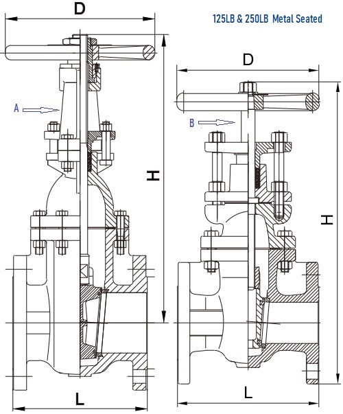
G.A drawings for MSS SP 70 Class 125 and Class 250 metal seated gate valves, made of ASTM A126 Gr.B gray iron, RF flanged. A: OS&Y rising stem, B: non-rising stem.
Cast iron gate valves designed in accordance with MSS SP 70 shall be furnished with ASTM A126 Grade B gray iron bodies and bonnets. Two classes are available: Class 125 and Class 250. We supply Class 125 in both rising stem and non-rising stem styles; Class 250 is only available in rising-stem style. Although MSS SP 70 permits the resilient seating design, generally the valve will be provide with metal-to-metal seating with one-piece solid wedge. The purpose of the wedge is to introduce a high supplementary seating load that enables metal-seated wedge gate valves to seal not only against high, but also low, fluid pressures. The wedge seating surfaces are separate brass or bronze rings securely fastened to the disc (wedge). The body seats shall be separate brass or bronze rings bottom seated/ mounted on the valve body. The end connection shall be either flanged or threaded, according to ASME B16.1 or ASME B1.20.1, respectively. Valves bodies and bonnets shall meet the minimum wall thickness requirements specified in ASME B16.1 for the same NPS and Class gray iron fitting. Face-to-face dimensions of flanged end valves shall be in accordance with ASME B16.10.
| Valve Part | Material |
|---|---|
| Body | ASTM A216 Gr.B |
| Bonnet | ASTM A216 Gr.B |
| Wedge | ASTM A216 Gr.B |
| Seat Ring on Wedge | ASTM B62 C83600 |
| Seat Ring on Body | ASTM B62 C83600 |
| Stem | ASTM B16 C36000 AISI 420 |
| Packing | Graphite |
| Handwheel | ASTM A126 Gr.B |
| NPS | L mm | H mm | D mm |
|---|---|---|---|
| 2" | 178 | 375 | 178 |
| 2-1/2" | 190 | 422 | 178 |
| 3" | 203 | 475 | 200 |
| 4" | 229 | 606 | 254 |
| 5" | 254 | 683 | 300 |
| 6" | 267 | 828 | 300 |
| 8" | 292 | 1003 | 348 |
| 10" | 330 | 1211 | 400 |
| 12" | 356 | 1421 | 457 |
| 14" | 381 | 1641 | 560 |
| 16" | 406 | 1828 | 560 |
| 18" | 432 | 2047 | 610 |
| 20" | 457 | 2246 | 610 |
| 24" | 508 | 2632 | 765 |
| NPS | L mm | H mm | D mm |
|---|---|---|---|
| 2" | 216 | 384 | 175 |
| 2-1/2" | 241 | 436 | 200 |
| 3" | 283 | 492 | 254 |
| 4" | 305 | 610 | 300 |
| 5" | 381 | 715 | 300 |
| 6" | 403 | 812 | 348 |
| 8" | 419 | 1024 | 400 |
| 10" | 457 | 1211 | 457 |
| 12" | 502 | 1386 | 457 |
| NPS | L mm | H mm | D mm |
|---|---|---|---|
| 2" | 178 | 302 | 178 |
| 2-1/2" | 190 | 332 | 178 |
| 3" | 203 | 335 | 200 |
| 4" | 229 | 423 | 254 |
| 5" | 254 | 485 | 300 |
| 6" | 267 | 545 | 300 |
| 8" | 292 | 644 | 348 |
| 10" | 330 | 769 | 400 |
| 12" | 356 | 860 | 457 |
| 14" | 381 | 987 | 560 |
| 16" | 406 | 1044 | 560 |
| 18" | 432 | 1148 | 610 |
| 20" | 457 | 1257 | 610 |
| 24" | 508 | 1418 | 765 |
A shell test and a hydraulic seat test shall be made on all completed valves prior to shipment. A gas seat test may be done upon buyer’s request.
In the shell test, the gray iron gate valve in partially open position with both ends sealed shall be subjected to hydrostatic or gas test pressure specified in Table A. No visible leakage is permitted through the pressure boundary walls or body-bonnet joint. The test pressure shall be held for the duration specified in Table B.
| Max. Service Rating @150°F | Test Pressure Minimum |
||
|---|---|---|---|
| psi | bar | psi | bar |
| 150 | 10.3 | 265 | 18.3 |
| 200 | 13.8 | 350 | 24.1 |
| 300 | 20.7 | 525 | 36.2 |
| 500 | 34.5 | 875 | 60.3 |
| NPS | Shell Test Duration (seconds) | Seat Test Duration (seconds) |
|---|---|---|
| 2"~8" | 30 | 30 |
| 10"~18" | 60 | 60 |
| 20"~24" | 180 | 120 |
Valves shall be subjected to a hydraulic seat test at not less than the maximum service pressure for which the valve is rated. Test pressure shall be applied successively on each side of the closed gate, and the opposite side checked for leakage. The maximum permissible leakage rate on each seat shall be 10 ml/hr/NPS. Test pressures shall be held for periods specified in Table B. When a gas seat test is performed, the test pressure shall be not less than 80 psi [5.5 bar] in lieu of hydraulic seat test. The maximum permissible leakage rate for each gate seat shall be 0.1 scf/hr/NPS (2.8cc/hr/NPS). Test pressures shall be held for periods specified in Table B.