Categories
- Pipe & Tube (18)
- Flange & Fitting (97)
- Fastener & Gasket (12)
- Valve & Pump (18)
- Base Material (11)
- Equipment (10)
- Application (31)
- Technical (110)
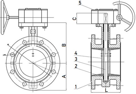
Technical G.A. drawing of MSS SP 67 flanged butterfly valves, worm gear operated, pinned disc, concentric design.
The MSS SP 67 flanged butterfly valve has two integral flanges cast on the body that is either made of ductile iron or cast grey iron. The two integrally cast end flanges can match the standard piping flanges with internal room between the flanges for bolting (Thus, it is also known as “double-flanged” butterfly valves). Compared to wafer and lug design, the flanged body has larger face-to-face dimensions and is usually used with larger-size butterfly valves, which are more apt to leak from thermal expansion. According to MSS SP 67, there are two face-to-face patterns: long pattern (wide pattern) and short pattern (narrow pattern). As illustrated in Figure-A, item 2 is the end flange cast integrally on the valve body, which is bolted up with the pipe flange (item 1) by using bolts and nuts (item 3) to install the flanged butterfly valve (II) to the piping (I & I’).
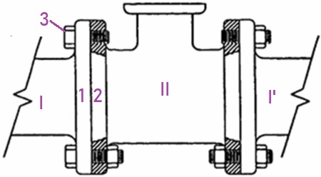
Figure-A: The illustration of bolting connection of flanged butterfly valve to the piping.
Design features of cast iron or ductile iron flanged butterfly valves made in accordance with MSS SP 67: (1) various operation methods: worm gear, handle lever, pneumatic/electric/hydraulic actuator; (2) concentric (centerline) design; (3) rubber lined seat; (4) pinned disc; (5) double flanged end connection; (6) tight shut-off sealing (zero fluid leakage). The flanged ends shall be compatible for use with flanges conforming to: ASME B16.1 Class 25 or Class 125; ASME B16.5 Class 150; ASME B16.47 Series A Class 150; ASME B16.24 Class 150; ASME B16.42 Class 150; or AWWA C-207.
| Item No. | Main Part | Material |
|---|---|---|
| 1 | Body | Cast Iron Ductile Iron |
| 2 | Seat | EPDM, NBR |
| 3 | Stem | SS 304, SS 316, SS 416, SS 431 |
| 4 | Disc | D.I. + Ni Plated SS 304, SS 316 Bronze, Al-Bronze |
| 5 | Gear | Carbon Steel |
The valve body shall be made from ductile iron of ASTM A536 Grade 60-40-18 or Grade 65-45-12, or cast grey iron of ASTM A126 Class B. The cast iron body shall be used with upper and lower temperature limits of 210°C [410°F] and -5° [-20°F], respectively. The ductile iron body shall be used with upper and lower temperature limits of 345°C [650°F] and -5° [-20°F], respectively. The soft seat shall be made from EPDM or NBR rubber. The applicable working temperature ranges for EPDM and NBR are -20°C~110°C and -10°C~80°C, respectively.
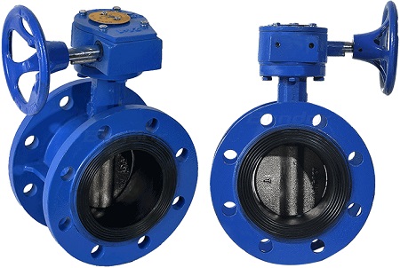
MSS SP 67 worm gear operated ductile iron butterfly valves, double flanged ends, pinned disc, epoxy painted, EPDM rubber lined seat.
| Size | A inch | B inch | C inch | L (short) inch | L (long) inch |
|---|---|---|---|---|---|
| 3" | 3.82 | 5.16 | 1.18 | 5.00 | 5.00 |
| 4" | 4.69 | 5.91 | 1.18 | 5.00 | 7.00 |
| 6" | 6.14 | 7.09 | 1.26 | 5.00 | 8.00 |
| 8" | 7.36 | 8.27 | 1.57 | 6.00 | 8.50 |
| 10" | 8.20 | 8.67 | 1.97 | 8.00 | 15.00 |
| 12" | 9.86 | 10.83 | 1.97 | 8.00 | 15.00 |
| 14" | 11.42 | 12.91 | 1.97 | 8.00 | 16.00 |
| 16" | 12.63 | 14.80 | 2.76 | 8.00 | 16.00 |
| 18" | 13.52 | 16.01 | 3.35 | 8.00 | 16.00 |
| 20" | 16.08 | 17.64 | 3.74 | 8.00 | 18.00 |
| 24" | 18.78 | 20.39 | 4.33 | 8.00 | 18.00 |
| 30" | 20.33 | 24.02 | 3.74 | 12.00 | 22.00 |
| 36" | 24.21 | 27.24 | 5.00 | 12.00 | 22.00 |
| 42" | 28.74 | 34.06 | 5.12 | 12.00 | 24.00 |
| 48" | 39.40 | 34.80 | 5.91 | 15.00 | 26.00 |
| 54" | 45.70 | 39.20 | 7.87 | 15.00 | 28.00 |
| 60" | 50.10 | 41.80 | 7.87 | 15.00 | 30.00 |
| Size | Holding Time |
|---|---|
| ≤2" | 15 |
| 2-1/2“~8” | 60 |
| ≥10“ | 180 |
Each assembled valve shall be subjected to a pressure test at a minimum of 1.5 times the body design cold working pressure for the duration specified. This shell test shall be made with water which may contain a corrosion inhibitor. No visible leakage through the body wall shall be allowed.
| Size | Holding Time |
|---|---|
| ≤12" | 15 |
| 14"~24" | 30 |
| ≥24“ | 60 |
Each valve shall take the seat test, which is also called “sealing test”, at the fully closed position to a pressure equal to at least the rated system pressure for the duration specified above. The test shall be made with water which may contain a corrosion inhibitor and shall be conducted in a manner that will test the tightness of the seat in the direction of flow. This test shall be made at ambient temperature with the seats clean and free of oil, grease, or any sealant.