Categories
- Pipe & Tube (18)
- Flange & Fitting (97)
- Fastener & Gasket (12)
- Valve & Pump (18)
- Base Material (11)
- Equipment (9)
- Application (31)
- Technical (110)
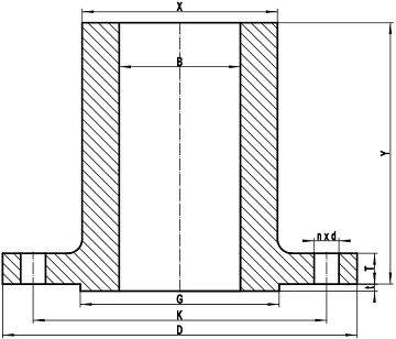
Figure-1: a typical drawing for long welding neck flange with raised face made in accordance with ASME B16.5
ASME B16.5 has endorsed the design of long welding neck flange (LWN), which is also known as straight hub welding flange. The LWN flange is constructed by two sections: the upper section is a heavy-wall barrel, whilst the lower section is a disc-like plate flange with all dimensions conforming to ASME B16.5 standard flanges.
The long welding neck flange is mainly applied to the construction of pressure vessel functioning as a nozzle (such as a thermowell nozzle). To attach a common welding neck flange to a pressure vessel, a piece of pipe is required with additional welding. A LWN flange on the other hand attaches directly to the vessel, hence, it can be viewed as an integrally reinforced nozzle. It avoids making a weld seam at pipe to flange and provides self-reinforcement.
Generally, long weld neck flanges (straight hub welding flanges) conforming to ASME B16.5 have hubs of uniform thickness unless otherwise specified by purchaser. The dimensions illustrated in Figure-1 are as follow: D – outside diameter of flange, K – diameter of bolt circle, G – diameter of raised face, B – bore diameter of flange, X – diameter of hub, Y – length through hub, T – flange thickness, t – height of raised face, n – number of bolts, d – diameter of bolt hole. The LWN flanges shall have dimensions and tolerances of the standard welding neck flanges of the same size and class, except that the length through hub shall be 229 mm (9″) for NPS 4 and smaller and 305 mm (12″) for larger than NPS 4. The LWN flange shall be provided with square cut end unless otherwise specified by the purchaser. Particularly, the dimensional tolerance for X (diameter of hub) is (+3.0 mm, -0.0 mm).
The weight of a long welding neck flange can be calculated by using the following equation: Mass = [ ( X + B ) / 2 * ( X – B ) / 2 * 0.0246615 * ( Y – T ) * 10-3 ] + [ ( D2 – B2 – nd2 ) * T + ( G2 – B2 ) * t ] * 6.165375 * 10-6, Assume that the flange is made of carbon steel.