Categories
- Pipe & Tube (18)
- Flange & Fitting (97)
- Fastener & Gasket (12)
- Valve & Pump (18)
- Base Material (11)
- Equipment (10)
- Application (31)
- Technical (110)
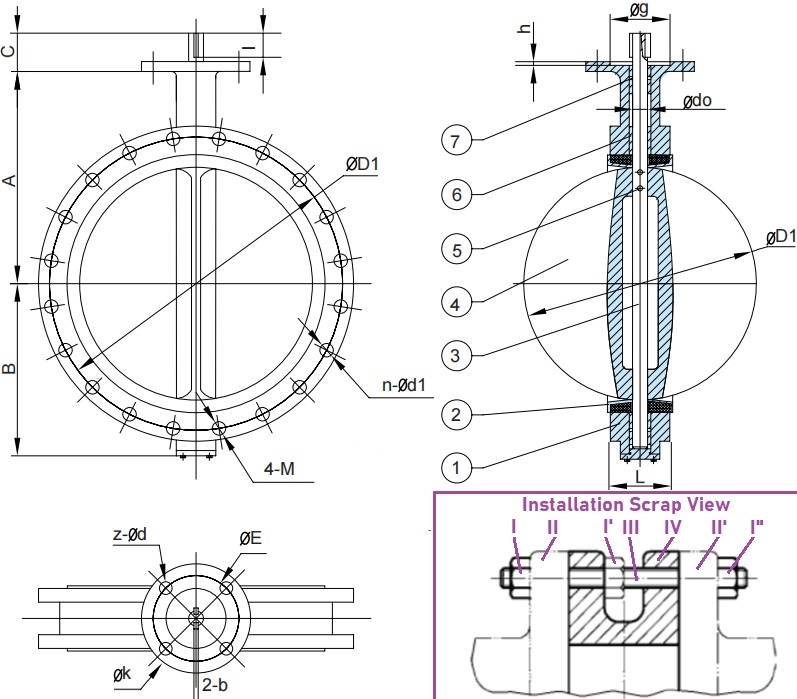
The technical G.A. drawing of an U-section butterfly valve with double flanged ends, bare stem with ISO 5211 mounting flange, pinned disc, designed to EN 593 & BS 5155. The scrap view of installation of such a valve in piping systems.
As specified by EN 594 and BS 5155, the U-section butterfly valve is a wafer-style valve with two flanged ends. Unlike the conventional double-flanged butterfly valve, although two integral flanges are integrally cast on the body, the internal space between the two integral flanges are too small for them to be bolted up with pipe flanges from each side respectively. In short, the face-to-face dimension is relatively much smaller. Thus, it requires a through-bolt connection when it is installed between two pipe flanges. As illustrated in the “Installation Scrap View”, the U section butterfly valve (item IV) is sandwiched between two piping flanges (items II and II’) by using the through stud (item III) and three hex nuts (items I, I’ and I”). The section view of the valve resembles the capital letter “U”, the reason it is called U-section butterfly valve. Compared to lug-style body, the bolt holes of the integral flanges are not threaded holes; Compared to conventional wafer-style body, the complete drilling pattern provides convenient alignment and easy assembly.
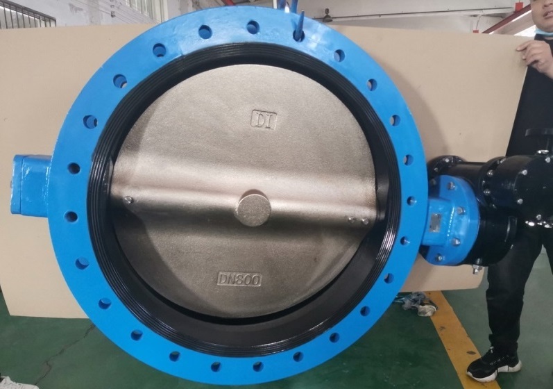
A ductile iron body U section butterfly valve designed to BS 5155, worm gear operated, DN800 PN10. Pinned concentric design, nickel plated ductile iron disc, EPDM rubber lined seat.
Other design features of U section butterfly valve manufactured to EN 593 or BS 5155: (1) Concentric disc design: centerline alignment to that of the shaft. (2) Pinned disc: transmit torque from the shaft to the disc by using taper pins. (3) Applicable to larger sizes: usually available for sizes 12″ and above. (4) Light in weight, convenient installation and cost effective. (5) It not only can be used for on-off service in piping but also can be used in end of line service. The end of line service refers to the condition that occurs when the downstream side of the valve is opened to atmosphere. (6) ISO 5211 mounting flange provides connection to various manual or automated operators.
| Item | Main Part | Material |
|---|---|---|
| 1 | Body | Ductile Iron Cast Iron |
| 2 | Seat | EPDM, NBR Neoprene, VITON |
| 3 | Shaft | SS 304, SS 316 SS 410, SS 431 |
| 4 | Disc | D.I.+Ni Plated SS 304, SS 316 Al-Bronze |
| 5 | Taper Pin | SS 410 |
| 6 | Bushing | PTFE, Bronze |
| 7 | O-ring | EPDM, NBR |
| Size | B mm | A mm | C mm | L mm |
|---|---|---|---|---|
| 12" | 242 | 337 | 34 | 76 |
| 14" | 267 | 368 | 40 | 76 |
| 15" | 320 | 375 | 52 | 102 |
| 16" | 316 | 400 | 52 | 102 |
| 18" | 344 | 422 | 52 | 114 |
| 20" | 380 | 480 | 64 | 127 |
| 22" | 432 | 533 | 70 | 151 |
| 24" | 468 | 562 | 70 | 151 |
| 26" | 484 | 540 | 70 | 172 |
| 28" | 530 | 626 | 95 | 165 |
| 30" | 564 | 660 | 95 | 167 |
| 32" | 602 | 666 | 95 | 188 |
| 36" | 661 | 722 | 130 | 203 |
| 40" | 724 | 806 | 130 | 216 |
| 42" | 784 | 865 | 150 | 251 |
| 44" | 804 | 820 | 150 | 253 |
| 48" | 869 | 938 | 150 | 276 |
The drilling and facing dimensions of the end flange shall be machined in accordance one of the followings: BS 4504 PN10/PN16, BS 10 Table D/Table E, AS 2129 Table D/Table E, ASME B16.1 Class 125 & ASME B16.42 Class 150, ISO 7005-2 PN10/PN16, ASME B16.5 Class 150, AWWA C-207.